Tampilkan postingan dengan label keel. Tampilkan semua postingan

Sabtu, 31 Desember 2016

Raising the Keel

In early January, my dad and brother descended on the boat shop like Stormtroopers and raised the keel in no time using bottle jacks and one big truck jack. The keel was up to about 60 degrees when we decided to push her the rest of the way up. One big push and a rebel yell later, we had a keel! 

I wouldnt advise doing it this way, of course. The proper way would have been hooking her to some come-alongs to pull her the rest of the way up.


Read More..

Kamis, 16 Juni 2016

Making Keel Cooling For A Friend

A very good friend of mine had a new engine fitted recently.  The boat was an ex hire boat and only had a 35hp engine which is fairly normal for a hire fleet boat. The hire companies do this deliberately as they want to control the speed the boat can achieve and they probably govern the engine as well.

The beauty of these boats is they can be bought for very reasonable price, they come well equipped with quality fittings to stand the riggers of hire and the hulls are well built.

So the internal skin tank was set up for a 35hp engine, a fact the professional boat company installing the new 52hp engine somehow overlooked?  Hmm?! IMO the first thing to work out when fitting an engine is how to cool it.  If you cant cool it you cant run it.  Well you can but so long as you dont call up all the horses or want to destroy it. 

The problem only manifested itself when Sue needed to punch against the flow on the Thames, which of course needed more horses than poodling on a canal which she had been doing since the new install.

There were 2 options to solve this, another internal skin tank linked to the original which would require the engine bay to be cleared of things like the errr! engine!  The other option an external skin tank, or keel cooling which is really what a skin tank is requiring just 2 holes made and welded in the hull.  No engine removal and just a few hours work in a dry dock.

Theres a well regarded formula for working out the cooling area / engine hp.  Its HP divided by 4, so a 52hp engine needs 13sq/ft of surface area.  The most compact way of doing this is with tube, in this case 80 x 40 box section which gives 1sq/ft of surface area every 16" of length.  To further compact this a serpentine patten is the norm.

This is it.


So this is what I came up with and made for Sue & Vic.  See the links below as she takes up the story on her blog.  Read backwards from here:-  Sadly I wasnt able to fit it for her, but the local floating dry dock did a great job.

If you like boating blogs, you will love Sues.  Hers is constantly ranked in the top 10 UK boating blogs, its has a great balance of travelogue, opinion, and lifestyle showing the good and not shy of speaking about the not so good. Always punctuated with great photos and on the sidebars masses of excellent links, tutorials and resources as well as a massive list of fellow boater blogs.
Read More..

Minggu, 22 Mei 2016

Aligning Frames and Laying the Keel


After the confirmation that this boat will make it out of the basement, I secured my frame pieces to the leveled form rails. After checking a hundred times if things were square to each other, I aligned the stem using a string and plumb bob method. I tried a laser but it was better at confirming the set-up than actually doing it.
I used steel carriage bolts for the dry run set up of the keel and transom knee. When I was satisfied with alignments I took the keel and transom knee apart and did the glue-up. When all was, glued, bolted and screwed in place I called it a day. The next day I sighted down the keel and saw hump between frame #1 (middle frame and frame #2 (front frame), which wasnt a real issue, but there was a dip between the transom and frame #1 which was a problem. The picture is sighting down the keel from the front and the flash didnt illuminate the keel after the middle frame. After sleeping on it, I decided to try and realign the transom a bit to straighten the keel forward of the transom.
I decided to shim frame #1 rearward about 1/16" and this gave me some room between the transom and form to re-align it. I pulled a 1/16" shim out to lower the transom, added one at the top of the form angle to the transom and this allowed clamping of the transom near the bottom of the form and I could dial out the dip in the keel with a twist of the clamps. So with the keel flat from transom forward to frame #1, I could move on.
Read More..

Sabtu, 19 Maret 2016

Laminating the Keel

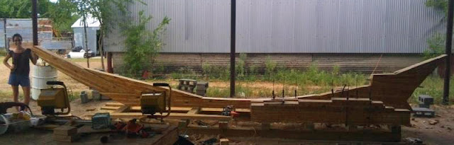
Once I had all the patterns I needed for the keel chunks, I assembled a cradle from 4x6s fastened with lag bolts and started laminating the pieces of keel from thinner stock. Several hundred board feet of Southern Yellow Pine 2x8s, 7 gallons of epoxy and 15 gallons of fumed silica later, I had my keel chunks laminated.

There were big lessons learned in the process:

1) I will need about 500 clamps to build this boat.

2) It would have been ideal to buy the construction grade lumber I used at the exact moment I needed it and no sooner. Even when stacked properly in a rather consistent climate (the desert), it tended to warp and twist and required all manner of cursing, cajoling, and sweet-talking to get it to laminate up into a straight chunk of wood. I guess its good to make due with what you have. If I waited for the perfect tools, the perfect materials, the perfect budget, and the perfect place to build, Id probably never get started.

3) Epoxy is not fun to work with. Laminating the keel with epoxy made the decision to plank the boat rather than use plywood easy.

As I laminated a piece, I traced the shape of the pattern on each face and cut them a little outside the lines with my Skillsaw. Then I took a chainsaw and cut down until I met the Skillsaw cuts on each side and then whacked off the chunks with a hatchet and chisel. A power planer was my best friend in getting the pieces true to shape.


Boat building in hindsight: For the next boat (a 50 ft. cargo junk schooner, perhaps?), I will definitely buy the timbers Ill need rather than laminate them from thinner stock-- it should be much cheaper and easier.
Read More..

Kamis, 10 Maret 2016

Keel Assembly

At some point during the blazing summer, the main keel timber twisted so much that if you looked aft down the timber, the left edge was about an inch off the cradle. I was in a sorry state of affairs for a couple of days after coming back from vacation and noticing this, but then just planed down the top surface of the timber so it was level again and proceeded with life as normal. This was the first in what I imagine will be a long line of oy vey occurrences in which I will need to remember that this is a boat, not a rocket ship.

After epoxying some of the deadwood and a fore knee to the main timber, I started looking around for ballast and floor bolts. I got really excited when I found a company selling galvanized timber bolts for cheap in Virginia and ordered a bunch from them. As an afterthought, I called back five minutes later and asked if the threads were cut or rolled. This is kind of a big deal because rolled threads would mean that Id have to drill a hole larger than the shaft of the bolt to get the thing through which means I would have little springs of water gurgling up through the keel into the hull. The very nice man who answered said that indeed they were rolled and cancelled my order for me. I ended up getting the bolts custom made by a company in Houston called Madden Bolt, and they did a fantastic job.

Here some of the keel chunks are glued together and I have the keel laid on its side to plane it down. I dont think Id drilled for the ballast and floor bolts yet. Note the curved thing in the foreground with all the clamps-- thats the deck beam mold.

Here the keel has been painted with copper naphthenate as a preservative, the ballast and floor bolts have been driven in, and some rebar is being zip-tied/wired to the ballast bolts to support the scrap metal that will be suspended in the concrete ballast.
Read More..
 
About Boat Plans - Powered By Blogger